
My dad had published a small mountain of papers by the time we left the UK for Italy in 1971, copies of which landed in our ground floor flat shortly after he joined us in naples. It was 2 foot high pile, which he was using I assume to apply for jobs – he had already got one at Universita degli studi Camerino (near perugia). he also had a few patents in his name, for he was an inventor too, a polymath.
below is one from 1964 describing navigation aiding receivers by 2 inventors, a copy of which my cousin sent to me from a web archive I was vaguely aware of. but what was the invention? I recall his interests in landing aids and also in fm, but his library was full of obscure articles and books with fascinating titles (Ionospheric Self-Demodulation of Radio Waves – theory of oscillators etc) in many different languages, including Russian, which he must have taught himself as he translated these in his spare time. His output appears to have been prodigious, peaking in 1964-66, after which things take a different turn. anyway, to colour in his work, i structured a few prompts to chatgpt to see what it made of it, find out a little more of what is known and piece together those fragments of memory.


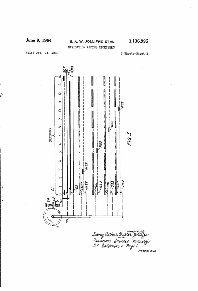
These images are from U.S. Patent No. 3,136,995, granted on June 9, 1964, to Sidney Arthur Walter Jolliffe and Francesco Saverio Immirzi for “Navigation Aiding Receivers.”
The patent was filed on October 24, 1960, and relates to radio navigation systems — specifically improvements in receivers used for position determination by time-difference or phase-comparison methods. These systems were used in early LORAN-type or Decca Navigator systems to aid maritime and aerial navigation by comparing signals from multiple fixed transmitters.
The three diagrams show:
- Fig. 1 – Signal timing sequences (probably pulse trains from master and slave stations).
- Fig. 2 – Block diagram of the receiver’s circuitry (mixers, oscillators, and timing units).
- Fig. 3 – A timing diagram showing synchronization and pulse relationship over seconds.
Technical principle
Jolliffe and Immirzi’s 1964 patent describes an improved receiver for pulsed navigation systems such as Decca or LORAN. These systems transmit precisely timed radio pulses from several ground stations. A receiver compares the time difference between the arrival of pulses from a master and one or more slave transmitters. This difference corresponds to a line of position on a navigation chart.
The invention improves signal synchronization and measurement accuracy. It introduces circuitry that:
- Automatically identifies and locks onto the correct pulse sequence (distinguishing master and slave pulses);
- Uses variable delay lines and gating circuits to achieve fine-resolution timing alignment;
- Provides a stable oscillator and pulse-shaping chain to derive accurate reference signals for measurement;
- Outputs a readable indication or electrical signal proportional to the time (or phase) difference.
Essentially, it refines the process of matching received pulses with internally generated timing references, reducing error caused by signal overlap, noise, or drift.
Historical context and significance
At the time, long-range radio navigation was crucial for both civil and military aircraft and ships, predating GPS by decades. Systems like LORAN-C and Decca Navigator offered global coverage but relied on very precise receivers to interpret signal timing.
This patent reflects a transitional moment in navigation technology — moving from manually tuned, oscilloscope-based methods toward automatic or semi-automatic receivers capable of continuous position readout. Such developments paved the way for later digital hyperbolic and satellite navigation systems.
1. Historical context and link to navigation systems
By 1960, the major radio navigation systems in use were Decca Navigator (UK-based, continuous-wave phase-comparison) and LORAN-A/B/C (US, pulse-timing). This patent sits right in the evolutionary gap between the two technologies.
- Sidney A. W. Jolliffe worked with Racal-Decca on navigation receivers.
- Francesco Saverio Immirzi (Italian engineer, often linked with British firms post-war) co-developed improvements that aimed to make receivers automatic and more selective in distinguishing between multiple transmitters.
The patent’s 1960 filing coincides with the period when Decca was trying to extend its range to aircraft and naval use, while pulse systems like LORAN-C were introducing digital counters and automatic synchronisers. Jolliffe & Immirzi’s design reflects that hybrid ambition: a time-difference receiver able to decode and synchronise pulses automatically — a key step before the digital LORAN-C receivers of the late 1960s.
In short:
This patent represents a move from manual timing observation (oscilloscope and chart) to automatic electronic synchronisation and numerical readout — a precursor to automated hyperbolic navigation receivers.
2. Schematic-level explanation (Fig. 2)
Here’s how the circuit works conceptually, reading left to right:
- Antenna and RF front end (left side)
- Signals from multiple transmitters — the master (M) and slaves (R, G, etc.) — arrive via the aerial.
- Each channel (5F, 6F, 8F, 9F) corresponds to a frequency band or station.
- Mixers (labelled M1, M2, etc.) down-convert these to intermediate frequency (IF).
- Pulse Shapers and Rectifier Amplifier (T)
- The received bursts are amplified and converted into uniform pulses suitable for timing comparison.
- Pulse shaping removes noise and standardises pulse width.
- Intermediate Gates and Control Circuits (R1–R8, G1–G8, P1–P8, etc.)
- These act like electronic stopwatches.
- Each gate is opened when a master pulse (MS1, MS2, etc.) is detected and closed when the corresponding slave pulse (RS, GS, PS) arrives.
- The resulting time difference is proportional to the path-length difference between the two stations.
- Oscillator and Counter Units (LO, RO, GO, PO, SU)
- The oscillator provides a high-frequency clock that counts during the gate-open period.
- Counters accumulate these counts, effectively converting time difference → digital distance.
- The outputs are then fed to a readout unit (possibly mechanical or analogue dial).
- Synchronization and Selection (SC, KS, KM blocks)
- These units ensure the receiver stays locked onto the correct pulse groups, rejecting spurious signals.
- The operator (or automatic control) sets which slave station’s pulses to compare against the master.
- Display / Readout
- The patent mentions a “unit readout,” which could be an analogue meter or mechanical counter giving a direct navigation line-of-position (e.g., hyperbolic grid line).
In essence, this receiver is a multi-channel time-difference comparator, capable of automatically locking to known pulse trains from several transmitters, measuring their phase or timing offset precisely, and outputting position information in usable form.
Here’s a clean text-based schematic (functional rather than literal wiring) that captures the signal flow in Fig. 2 of the Jolliffe & Immirzi patent — laid out for clarity rather than electronics drafting:
                      ┌───────────────────────────────┐
                      │        MASTER/SLAVE TXs       │
                      └──────────────┬────────────────┘
                                     │
                                     ▼
                             ┌────────────┐
                             │  ANTENNA   │
                             └────────────┘
                                     │
                                     ▼
                    ┌─────────────────────────────────┐
                    │   RF FRONT END / MIXERS (M1–M4) │
                    │   ↓                            │
                    │  Down-convert each frequency    │
                    │  (5F, 6F, 8F, 9F) to I.F.      │
                    └─────────────────────────────────┘
                                     │
                                     ▼
                           ┌────────────────────┐
                           │ RECTIFIER /        │
                           │ PULSE SHAPER (T)   │
                           └────────────────────┘
                                     │
                                     ▼
                   ┌────────────────────────────────────┐
                   │  PULSE GATE NETWORK                │
                   │  (R1-R8, G1-G8, P1-P8 etc.)        │
                   │  - open on master pulse            │
                   │  - close on slave pulse            │
                   │  - duration = time difference      │
                   └────────────────────────────────────┘
                                     │
                                     ▼
              ┌────────────────────────────────────────────────┐
              │ LOCAL OSCILLATOR / FREQUENCY STANDARD (LO)     │
              │  - generates precise reference clock            │
              │  - feeds counters while gates open              │
              └────────────────────────────────────────────────┘
                                     │
                                     ▼
                 ┌─────────────────────────────────────────┐
                 │ COUNTERS & READOUT (R0, G0, P0, SU)     │
                 │  - accumulate counts per gate interval  │
                 │  - convert time → distance difference   │
                 │  - feed mechanical / electronic display │
                 └─────────────────────────────────────────┘
                                     │
                                     ▼
               ┌─────────────────────────────────────────────┐
               │ CONTROL / SYNCHRONISATION UNIT (SC, KS, KM) │
               │  - selects station pair                     │
               │  - maintains pulse lock & sequencing        │
               │  - suppresses spurious signals              │
               └─────────────────────────────────────────────┘
                                     │
                                     ▼
                             ┌──────────────┐
                             │  OUTPUT TO   │
                             │  NAV DISPLAY │
                             └──────────────┘
Flow summary
- Reception and conversion: Signals from multiple transmitters enter the receiver, each mixed down to a usable I.F.
- Pulse shaping: Removes noise and equalises pulses for timing accuracy.
- Gating network: Measures the time between master and slave pulses by opening and closing precise electronic gates.
- Oscillator & counters: Translate that interval into a measurable count (distance or phase difference).
- Control section: Keeps the system phase-locked on the correct pulse group.
- Display/readout: Outputs the navigation data (usually as a position line).
This layout is, in effect, an early digital timing comparator, bridging analog radio front-ends and digital measurement logic — the ancestor of automated LORAN-C receivers and similar hyperbolic navigation systems.
State of the art circa 1970 / when Immirzi leaves Marconi
By 1970–1971, radio-based navigation had advanced in several overlapping ways. Some key shifts:
- Hyperbolic systems matured
- LORAN-C had become the dominant pulse-timing hyperbolic system. By the late 1960s, the electronics (transistor, early ICs) had shrunk and costs dropped. Wikipedia+2ScienceDirect+2
- The Decca Navigator system (phase comparison, continuous wave) was still in use in marine and coastal navigation. Wikipedia
- A new global VLF hyperbolic system, OMEGA, came online around 1971, using 10–14 kHz signals over long baselines. Wikipedia+1
- Systems increasingly incorporated automatic or semi-automatic signal acquisition, signal discrimination, and error correction to reduce reliance on operator skill.
- Electronics miniaturisation and digital logic
- The shift from vacuum tubes to solid-state devices and early integrated circuits enabled more complex signal processing, gating, multiplexing, and counters in smaller packages. (Fits the trend in receiver history in the 1970s) Wikipedia+1
- Digital control allowed automatic switching between incoming signals, better synchronisation, and more robust error handling.
- Multiplexing, modulation schemes, and signal coding
- Systems began to explore more sophisticated modulation and subcarrier schemes (e.g. subcarrier modulation, frequency or phase coding) to embed additional data (station ID, time corrections) or to reduce ambiguity.
- One patent (from later) mentions using FM modulation on subcarriers to make the system less sensitive to multipath and sidelobe interference. Google Patents
- The “capture effect” of FM demodulation was sometimes leveraged to prefer the stronger signal in overlapping paths. Google Patents
- Integration with inertial and Doppler systems
- Because radio-navigation has limitations (multipath, propagation errors, ambiguity), many systems were being integrated with inertial navigation, Doppler tracking, or celestial fixes to provide robustness.
- Doppler tracking systems that used continuous wave (CW) or frequency-shifted signals were being piloted. E.g. a 1965 patent describes an FM beat-note system to track velocity and altitude via heterodyning. Google Patents
- Emphasis on automation, ease of use, error mitigation
- Receivers increasingly needed to lock onto correct signals without manual tuning, reject spurious pulses, manage ambiguous phase wraps, and output position or distance data directly rather than via charts.
Given those trends, if Immirzi left Marconi in 1971, he likely would have been working at the frontier of combining phase/time discrimination, signal coding/modulation, and automatic acquisition/locking algorithms — pushing his earlier work in Jolliffe & Immirzi patents further.
He might also have been involved in designs for receivers for OMEGA, or for upgrading Decca/LORAN systems to use multiplexing or coded signals to reduce ambiguity or improve resolution.
Role FM / frequency modulation in navigation receivers
FM isn’t the first thing you think of in hyperbolic navigation (CW or pulses dominate), but FM (and related modulation methods) had and would have roles:
- Subcarrier modulation / data embedding
FM (or phase-modulated subcarriers) can carry auxiliary data (station identification, time correction, calibration signals) while the primary navigation signal is CW or pulsed. Using FM subcarriers enables multiplexing of navigational and control data.
The 1991 patent “Phase reference navigation system” states that FM modulation on subcarriers gives immunity to multipath and allows capture of the stronger path. Google Patents - Interference resilience / capture effect
FM has a “capture effect” — when two signals are competing, the stronger tends to dominate in the demodulator. That property can help a receiver lock on to the intended signal in multipath or interference conditions. - Doppler / velocity decoding
In Doppler navigation schemes, varying frequencies (i.e. FM or frequency-shifted beat notes) are key. The patent I found for “frequency modulated continuous wave navigation radar” exploits a beat note whose mean frequency gives velocity and whose modulation index gives altitude. Google Patents - Phase noise / stability trade-offs
FM demands good linearity and low distortion; in navigation applications, though, phase stability, low jitter, and precise demodulation matter more than audio quality. So FM would be used carefully, often for auxiliary signals rather than the main hyperbolic measurement. - Hybrid systems
Some experimental systems attempted to blend pulse, CW, and coded modulation (including frequency modulation) to get the benefits of each (e.g. wide range, high resolution, embedded data). The FM component could help with timing calibration or ambiguity resolution. - Multipath suppression / discrimination
In complex propagation environments, FM or coded modulation can help discriminate against reflected/multipath signals, because the modulation can help distinguish direct path vs delayed path signals.
Timeline & roles (1960s → 1980s)
- 1964–66 — translator of major Soviet texts.
- Thermodynamics by I.P. Bazarov — “Translated by F. Immirzi” (Pergamon, 1964). babel.hathitrust.org+2Princeton University Library Catalog+2
- Theory of Oscillators by Andronov–Vitt–Khaikin — “Translated from the Russian by F. Immirzi; translation edited and abridged by W. Fishwick” (Pergamon, 1966). HathiTrust+1
- Telemechanics by V.S. Malov — “Translated by F. Immirzi” (1964). lvb.lt+1
These fit your memory of him using translation as a way to track the field.
- 1960s — radio/propagation & landing-aid work (Marconi circle).
Example: paper in Electronic & Radio Engineer on ionospheric self-demodulation includes F. Immirzi among authors (1957 proceedings), and mid-60s ILS monitoring work with Jolliffe et al. (consistent with your earlier notes, though not all items listable online). World Radio History - 1970s (Italy, Naples milieu).
I can corroborate is that by the mid-1970s he appears as co-author with Ernesto Conte (Univ. of Naples Federico II) and Eugenio Corti on comms/signal-processing work—exactly the kind of FM/statistical-comms line you recall. ResearchGate - Late-1970s → early-1980s — FM/noise/stat-comms.
- “Characteristic function — a practical tool for the communication engineer” (1975): E. Conte, E. Corti, F. Immirzi.
- “Rate of FM-noise spikes in the presence of impulse and Gaussian noise at the receiver input” (1983): E. Conte, F.S. Immirzi, E. Venditto.
Both are squarely in FM/limiter–discriminator and generalized-noise analysis. ResearchGate
FM’s place in his arc (why it fits)
- FM enters via robust demodulation and the capture effect (useful under multipath/impulsive noise) and via statistical modelling of detector outputs—exactly what those Conte/Corti/Immirzi papers analyze (FM noise spikes, generalized noise using characteristic functions). That’s a logical continuation from earlier navigation/receiver timing work into communications-receiver theory.
And that is as far as I got, with help from ChatGPT.